Here’s an automatic water pump controller circuit that controls the water pump motor. The motor gets automatically switched on when water in the overhead tank (OHT) falls below the lower limit.
Similarly, it gets switched off when the tank is filled up. Built around only one NAND gate IC (CD4011), the circuit is simple, compact, and economical. It works on a 12V DC power supply and consumes very little power.
The circuit can be divided into two parts:
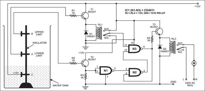
- Advertisement -Let us consider two reference probes ‘A’ and ‘B’ inside the tank, where ‘A’ is the lower-limit probe and ‘B’ is the upper-limit probe. The 12V DC power supply is given to probe C, which is the limit for minimum water always stored in the tank.
The lower limit ‘A’ is connected to the base of transistor T1 (BC547), the collector of which is connected to the 12V power supply, and the emitter is connected to relay RL1. Relay RL1 is connected to pin 13 of NAND gate N3.
- Advertisement -Similarly, the upper-limit probe ‘B’ is connected to the base of transistor T2 (BC547), the collector of which is connected to the 12V power supply, and the emitter is connected to pins 1 and 2 of NAND gate N1 and ground via resistor R3.
The output pin 4 of NAND gate N2 is connected to pin 12 of NAND gate N3.
The output of N3 is connected to input pin 6 of N2 and the base of transistor T3 via resistor R4.
Relay RL2 connected to the emitter of transistor T3 is used to drive the motor.
If the tank is filled below probe A, transistors T1 and T2 do not conduct and the output of N3 goes high. This high output energizes relay RL2 to drive the motor and it starts pumping water into the tank.
When the tank is filled above probe A but below probe B, water inside the tank provides base voltage to drive transistor T1 and relay RL1 energizes to make pin 13 of gate N3 high.
However, water inside the tank does not provide base voltage to transistor T2, so it does not conduct and the logic built around NAND gates N1 and N2 outputs low to pin 12 of gate N3. The net effect is that the output of N3 remains high and the motor continues pumping water into the tank.
When the tank is filled up to probe B level, water inside the tank still provides base voltage to transistor T1 and relay RL1 energizes to make pin 13 of gate N3 high.
At the same time, water inside the tank also provides base voltage to drive transistor T2 and the logic built around NAND gates N1 and N2 outputs high to pin 12 of gate N3. The net effect is that the output at pin 11 of N3 goes low and the motor stops pumping water into the tank.
When the water level falls below probe B but above probe A, water inside the tank still provides base voltage to transistor T1 and relay RL1 remains energized to make pin 13 of gate N3 high.
However, transistor T2 doesn’t conduct and the logic built around NAND gates N1 and N2 outputs high to pin 12 of N3. As a result, the output of N3 remains low and the motor remains stopped.
When the water level falls below probe A, both transistors T1 and T2 do not conduct. NAND gate N3 gives a high output to drive relay RL2 and the motor restarts pumping water into the tank.
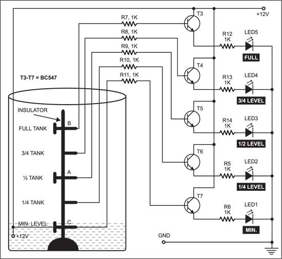
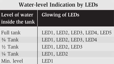
Fig. 2 shows the indicator/monitoring circuit. It consists of five LEDs, which glow to indicate the level of water in the overhead tank. Since a 12V power supply is given to water at the base of the tank, transistors T3 through T7 get base voltage and conduct to light up the LEDs (LED5 down through LED1).
When the water in the tank reaches the minimum at level C, transistor T7 conducts and LED1 glows.
When the water level rises to one-fourth of the tank, transistor T6 conducts and LED1 and LED2 glow.
When the water level rises to half of the tank, transistor T5 conducts and LED1, LED2, and LED3 glow.
When the water level rises to three-fourths of the tank, transistor T4 conducts LED1 through LED4 glow.
When the tank is full, transistor T3 conducts and all five LEDs glow. So, from the glowing LEDs, one can know the water level in the tank (see the table). The LEDs can be mounted anywhere for easy monitoring.
Note
The user can adjust the level to which water must be filled in the tank by adjusting the heights of probes A and B. The stand and adjusting screws should be insulated to avoid shorting.
This article was first published on 3 October 2004 and was updated on 28 December 2022.